IV. Process design and planning for bevel gears
I have been engaged in the research of manufacturing technology for bevel gears for a long time. There are a large number of relevant articles in this official account for you to understand, so I will not describe the relevant technical details in detail. There are many types of bevel gears, which can generally be distinguished by various dimensions such as axis intersection angle, tooth length curve form, machining form, and tooth height contraction form in the tooth length direction. They are widely used in vehicles, construction machinery, reducers, hand tools, and military equipment for special purposes. This article does not discuss some special structures or special applications such as bevel gears with high reduction ratio, axis intersection angle not 90 degrees, and their manufacturing processes.

Spur bevel gears are generally used in vehicle differentials and some electromechanical devices to change the direction of transmission or to achieve differential action. Currently, there are two manufacturing processes: one is machining, and the other is forming methods such as forging, powder metallurgy, and casting. The pre-heat machining process for spur bevel gears generally involves rough forging, rough turning, gear shaving, or gear broaching. The advantage of gear shaving is its high flexibility and low cost, making it suitable for single-piece or small-batch repair, or prototype trial production. The gear broaching process developed by Gleason and Klingelnberg uses disc cutters to achieve single-sided or double-sided machining, and can modify the tooth surface, making it an important method for high-precision small-batch processing of spur bevel gears. Gleason has launched the Coniflex Pro design and manufacturing system, while Klingelnberg has launched the Hypoflex spur bevel gear design and manufacturing system, further advancing the manufacturing process of spur bevel gears.
The straight bevel gears used in automotive differentials are in high demand and have relatively fixed product specifications. The tooth profile is generally produced using precision forging. The precision forging process mainly employs precise molds made by electric discharge machining (EDM). The management of mold life and consistency control are crucial. The precision forging process for straight bevel gears generally includes precision warm forging and precision cold sizing, achieving a forming accuracy of DIN 6-8 grade. The forging blank is typically a 20CrMnTi gear steel bar. The mold material is H13 electroslag remelting hot forging die steel, with a surface hardness of 48-51HRC after precision machining.

In terms of mold material selection, depending on the working temperature, high-temperature alloy materials such as high-temperature heat-resistant hot work die steel and high-temperature alloy steel can be chosen, as these materials can maintain high hardness and strength at high temperatures. Secondly, during the heat treatment process of mold steel, multiple pre-treatments such as hot upsetting and forging, multiple tempering processes, and thorough quenching can be employed to enhance the hardness and toughness of the mold steel, thereby improving the heat resistance and durability of the mold. The surface coating of hot forging molds is also one of the important means to improve mold life and performance. By coating the mold surface with one or multiple layers of specific materials to form a matrix structure with a certain hardness gradient, the wear resistance, thermal fatigue resistance, corrosion resistance, and friction coefficient of the mold can be effectively improved, thus significantly enhancing the mold's service life and work efficiency. In terms of equipment and tooling, the cooling system of the mold can be improved to ensure uniform heat dissipation during use and reduce the thermal load on the edge parts. Overall, enhancing the life of hot forging molds requires comprehensive consideration of multiple factors, including materials, processes, equipment, design, and maintenance. Through reasonable selection and optimization, the durability of the mold can be significantly improved, production costs can be reduced, and production efficiency can be enhanced.
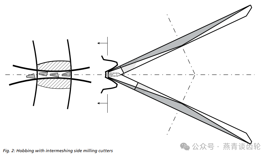
Regarding the machining process of spiral bevel gears, there are currently two commonly used tooth systems: tapered teeth and constant tooth height, which also feature tooth heights that decrease from the large end to the small end along the tooth length direction. During the machining process, the trajectory of the cutting edge of the tool blade is equivalent to one tooth of an imaginary generating wheel, and the resulting tooth length curve is an arc. After machining each tooth, the workpiece undergoes a tooth splitting motion until all gear teeth are machined. Common methods include the "five-cut method": two milling processes are used for the rough and finish cutting of the driven wheel; three processes are required for the rough cutting, finish cutting of the concave surface, and finish cutting of the convex surface on both sides of the driving wheel; and the "full-process method": a strip-shaped pointed tooth tool is used, and the tooth surface machining of the driving and driven wheels is completed in one clamping. Long-amplitude epicyclic bevel gears are generally constant tooth height bevel gears, and the workpiece undergoes continuous indexing during the machining process, where the tool head rotates a set of teeth and the workpiece rotates one tooth.
Regarding when to choose constant-pitch gears and when to choose tapered gears, I personally believe that there is no need to be overly obsessed. It requires comprehensive consideration based on the actual equipment, production capacity, proficiency of personnel, and industry development trends of the company. About fifteen years ago, the application of constant-pitch gears had not yet been fully rolled out domestically, and the five-cut method and full-process method of tapered gears were still predominant. The application of constant-pitch gears was mainly concentrated in some German joint venture automobile companies. Later, with the continuous deepening of openness, especially the continuous advancement of joint venture projects involving German heavy-duty trucks such as Mercedes-Benz, MAN, and Scania, the application scope of constant-pitch gear cones began to gradually expand, sparking a trend of "constant-pitch gear substitution". In any case, both processes can enable products to meet the required service strength, lifespan, and overall noise requirements. Therefore, we cannot arbitrarily deny that one technology is backward or more advanced; they are merely two different implementation paths.
The design, manufacturing, and testing technology of spiral bevel gears, as well as the setting of cutting tools and machining parameters, constitute a complete technical closed-loop process. Before the advent of computers, multiple iterative calculations were generally used to obtain relevant parameters. When machining with mechanical machine tools, tool adjustment was entirely manual, requiring manual adjustment of various parameters, and the use of change gears, feed change gears, and rotary table change gears, which involved a large amount of calculation, complex adjustment, and significant errors. At that time, the adjustment and product change of a bevel gear milling machine absolutely required experienced employees with high technical skills to complete.
Gleason and Klingelnberg, two internationally renowned manufacturers of bevel gear milling equipment, have virtually monopolized all technologies related to bevel gears. Gleason has developed various models of mechanical gear milling machines, including NO.26, NO.116, and NO.609, while Klingelnberg has also developed equipment such as SKM2 and SM3, as well as models like 5C280 introduced from the former Soviet Union. These machines maintain high precision and their second-hand equipment was eagerly sought after by domestic gear companies in the 1990s. Domestic companies, represented by Tianjin First Machine Tool Group, have successively imitated models such as YK2250 and YK2280. Harbin First Tool, Hanjiang Tool, and other companies have also acquired the ability to design and manufacture cutter heads and cutter bars. State-owned gear factories, represented by FAW, Harbin Gear, Beichang Gear, and Qichang Gear, have cultivated a large number of technical talents and become the backbone of domestic bevel gear manufacturing process development and technological innovation.
Later, with the advancements in numerical control technology and software, the calculation of relevant tooth surface parameters, equipment adjustment parameters, and precise tooth surface modification became the main working methods. Since 2005, Gleason Corporation and Klingelnberg Company have successively launched GAGE software and KIMOS software, respectively, equipped with their respective HC600 gear milling machine, C50 gear milling machine, as well as tool grinding and installation equipment. Together with M&M and P series gear testing centers, they have formed a complete solution for bevel gear technology, and have generally achieved dry cutting technology in the gear milling process, reducing a significant amount of cutting oil consumption and improving the working environment. However, the one-time equipment procurement cost is relatively high. A single set of equipment includes two gear milling machines, one measuring machine, one tool grinding machine, one tool loading device, and the related supporting KIMOS or GAGE software, with a minimum cost of 30 million RMB.


Following the large-scale expansion of the domestic heavy-duty truck, light-duty truck, light vehicle, bus, and construction machinery industries after 2008, a steady stream of related imported equipment has been introduced into the country, sparking a wave of investment. As of now, with the continuous penetration of new energy electric drive technology in related fields and the shrinking of market demand, the supply-demand imbalance in the traditional mid-to-low-end bevel gear market has intensified, leading to a severe shortage of operating rates. The only hope lies in the non-automotive industry and exports to the international market.
In terms of domestic bevel gear technology, with the digestion and absorption of introduced technologies and the guidance of innovative ideas from multidisciplinary integration, we have successively solved many technical challenges related to theoretical design, machining tools, tool grinding and installation, and precise tooth surface modification. We have carried out relevant research in line with China's national conditions and have completely resolved the bottleneck concerns. Manufacturers of domestic bevel gear process equipment, represented by Zhongda Chuangyuan, have partially replaced imported equipment in the market.
In terms of the technology for small modulus bevel gears, with the expansion of production capacity in electric tools and garden equipment, the demand continues to exist and is moving towards high-end development. Both Gleason and Klingelnberg have relatively mature solutions, such as Klingelnberg C15 and Gleason 100C, which, when paired with automatic loading and unloading mechanisms and chamfering programs, can achieve high-speed and high-efficiency production, with the takt time for a single piece being controlled within 1 minute. Domestic equipment, represented by Tianjin Jingcheng and Zhongshan Maileite, can also provide relevant alternative solutions, but their reliability and maturity still need to be verified.
When machining a left-handed gear with a left-handed cutter head, the cutting thickness increases from small to large, which is called counter milling. Counter milling results in faster wear of the cutting blade. When machining a right-handed gear with a left-handed cutter head or a left-handed gear with a right-handed cutter head, it is called conventional milling. Practice has proven that when the clamping force is reliable, conventional milling can improve the surface quality of the machined workpiece and enhance the durability and service life of the cutting blade.
When machining the same pair of gears, tool heads with different diameters can be selected. The characteristics of the machined gears vary depending on the diameter of the tool head. It is possible to determine the appropriate diameter using graphical methods, and the tool heads are classified into large diameter tool heads and small diameter tool heads. The characteristics exhibited when using a small diameter tool head for machining are: low sensitivity in the contact area, which remains relatively stable under large misalignment or load; small radius of curvature of the tooth length, resulting in good tooth strength; and certain limitations in gear lapping, as it can only be performed in the diagonal direction.
When the constant-mesh bevel gear is in the no-load condition, the driving side tooth surface should be near the midpoint of the tooth width, and the contact area should expand uniformly towards both ends after loading. The reverse gear contact area should be controlled slightly towards the larger end of the tooth width midpoint, and the trend of moving towards the smaller end after loading is faster than that towards the larger end.
Characteristics exhibited during machining with a large cutter head: As the diameter of the cutter head increases, the sensitivity of the contact area to V/H increases; when the center of the cutter head is outside the large end of the gear being machined, the effects of V/H movement on the contact area overlap; the gear lapping performance is good, allowing the lapping area to reach the tooth tip or tooth root positions at both the large and small ends, facilitating appropriate correction of the tooth contact area; under no-load conditions, the contact area should be controlled at the small end, and after loading, the contact area moves to the large end.
To machine a bevel gear, it is sufficient to determine three aspects. Firstly, the tool has a definite position in space. Secondly, the workpiece has a definite position in space. Thirdly, there exists a relative motion relationship between the tool and the workpiece. In terms of the tool, the installation angle of the tool, the rotation direction of the tool, and the geometric parameters of the tool head are all aimed at determining the position of the tool in space.
In terms of the workpiece, its tooth parameters, top and back cones, as well as the dimensions of the mounting surface, all serve to determine its spatial position. Additionally, when the tool is mounted on the machine tool, there is a tool tilt angle or tool rotation angle, as well as the initial and final table angles during tool generation, all of which are used to determine the tool's spatial position. The installation position of the workpiece on the machine tool, including horizontal wheel position, vertical wheel position, bed position, as well as tooling dimensions and installation distance, all contribute to determining the workpiece's spatial position.
The mutual motion relationship between the tool and the workpiece determines the tooth profile and tooth length curve of the machined gear: if the tool is parallel to the tip cone, the machined gear is of equal tooth height; if there is an angle between the tool plane and the tip cone surface, the machined gear is of tapered teeth. During the plunge method machining, the tool position has no other motion except for the feed in the tooth depth direction throughout the cutting process. During the generating machining, in addition to the feed of the tool in the tooth depth direction, there is also a feed of the tool center around the center of the machine tool's rocking platform during the cutting process.
To correct the tooth surface contact area, it is generally necessary to cut a portion of the small wheel locally. The specific part to be cut is determined by the initial design contact area. In order to achieve the purpose of cutting off a portion of the material from the small wheel, some additional movements need to be added, generally including helical movements, to make the rotation of the workpiece slightly faster or slower.
By changing the tooth profile of the tool, the specific position of the tooth surface contact area along the tooth height can be altered. By changing the amount and position of the tool's drum shape, the width and size of the contact area can be changed. Helical motion can be applied to either the tool or the workpiece. Drum shape and edge trimming are not the same thing. Drum shape refers to the tooth surface, while edge trimming generally refers to the tooth tip. By changing the starting and ending positions of the rocking platform during generation, as well as the generation angle, the size and width of the tooth surface contact area in the tooth length direction can be altered.
Looking at the tool adjustment section of the card, it can be divided into three main parts: first, the part related to tooth profile; second, the part related to tooth length; and third, the part related to the installation and adjustment of the cutter head.
The parameters related to tooth profile mainly include the cutting edge pressure angle, cutting edge drum shape, tooth root arc, tooth tip chamfer, tooth tip width, tooth tip arc, and tool offset. Those related to tooth length include the cutter head radius and the inner and outer cutter radii. Those related to the installation and adjustment of the cutter head include the cutter bar extension height, the height of the cutting edge of the cutter bar, the full height of the cutter bar teeth, and the tooth tip height. Additionally, some parameters are related to cutting performance, including non-cutting edge related parameters, such as the rake angle, relief angle, inclination angle of the cutting edge, and tool tip angle
Regarding tool design, several issues need to be avoided: ensuring that the machined tooth surface is not damaged by the other side of the blade; ensuring that the tool nose radius is intact and not interfered with by non-cutting edges; ensuring that the tooth root radius is intact, without the appearance of tooth base ridges or large tooth root undercuts. Regarding tool grinding, the two main aspects are to ensure that the geometric dimensions and angles of the tool blade itself conform to the initial design parameters; and to ensure consistency among the tool blades in the same group.
There is a common belief in the industry that constant-pitch bevel gears cannot be ground. This statement is both correct and incorrect. Generally speaking, constant-pitch gears refer to those with tooth length curves that are cycloidal. Due to their different machining principles from tapered gears, butterfly grinding wheels cannot perform continuous indexing, making grinding impossible. However, for constant-pitch gears with tooth length curves that are arcs, the principle is similar to that of machining tapered cylindrical gears, and grinding is possible using grinding wheels, although it is rarely adopted.
 中文
中文
 English